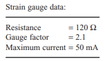
Four strain gauges, with specification given below, are available to measure the torque on a cylindrical shaft 4 cm in diameter connecting a motor and load.
(a) Draw clearly labelled diagrams showing:
(i) the arrangement of the gauges on the shaft;
(ii) the arrangement of the gauges in the bridge circuit, for optimum accuracy and sensitivity.
(b) Calculate the maximum achievable bridge out-of-balance voltage for an applied torque T of 103 N m given the following:
Tensile and compressive strains ![]() is the shear modulus of the shaft material and a is the radius of the shaft in metres.
is the shear modulus of the shaft material and a is the radius of the shaft in metres.